

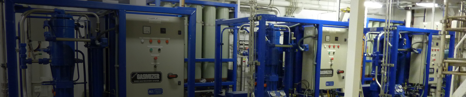
Electric Gasmizer
JFD's Gasmizer diver gas recovery system is the world’s most popular helium gas reclaim system with over 6,000,000 safe diving hours operation.
Comprising of four main robust components, the Gasmizer will reclaim gas from two divers from 500 metres (1650 feet). The purpose of the Gasmizer diver gas recovery system is to recover gas mixtures breathed by divers, re-process it and then redeliver it in to the supply system.
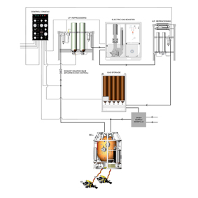
The gas is removed from the helmet as it is exhaled by means of a recovery valve. From there it is passed via the bell to the surface where the gas is scrubbed to remove carbon dioxide, filtered to remove moisture and any particulate or biological contaminant, and oxygen is added to give the desired breathing mix. The gas is compressed and delivered to storage until required for use, when it will be delivered to the bell gas supply console.
The system requires a minimum amount of equipment on the bell, so adding negligible weight and taking up little space. No electrical connections are required in the umbilical so there is no possibility of communications interference or electrical hazard underwater. As the major components are topside, it has been possible to design the system such that it may be serviced while a dive continues.
In addition to recovering divers gas, the system may be used to recycle bell gas thus reducing gas loss due to bell flushing.
The system has several levels of safety back-up. A conventional demand system is used and by means of a single action, open or closed circuit operation may be selected. Similarly, the conventional emergency bail-out system is available.
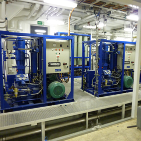
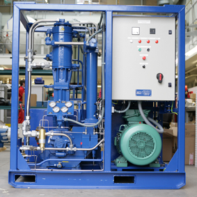
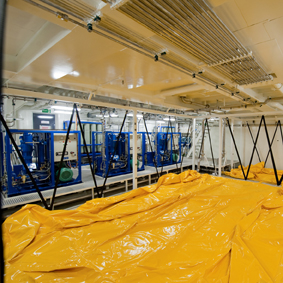
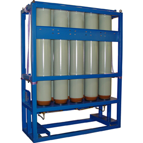
| Electric Gasmizer | Electric Gasmizer | Electric Gasmizer and gasbag | Gasmizer equipment layout | Gasmizer BPR in diving bell | BPR loader | Reprocessing units | Volume tank |
|
|
|
|
|
|
|
|
|
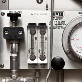
Exhaled gas is recovered from the divers by means of reclaim valves, mounted on helmets. The exhaust umbilicals are connected via SAECO valves (Supply Actuated Exhaust Cut-Off Valves) situated in the bell. Gas then passes via a water trap in to a back pressure regulator, which controls the pressure in the exhaust umbilical. The bellman can monitor this pressure on a gauge situated in the bell. Gas is then passed to the surface via a non-return valve and a second water trap.
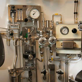
On the surface, the gas enters the reprocessing unit where oxygen is made up to the correct mix. The gas is then passed to an electric gas booster where the pressure is increased prior to returning to the reprocessing unit. It is then scrubbed to remove CO2 and other impurities before being passed to the volume tank for storage and eventual re-supply to the conventional gas supply system. This gas is passed via a bell umbilical to the bell gas supply manifold and then to the diver’s demand regulator.
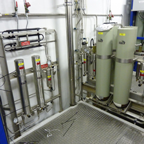
The addition of an optional second gas booster will allow 100% redundancy enabling continued operation during maintenance. Similarly two scrubber canisters are provided, either of which can be replenished while a dive continues.
During normal operations the oxygen used by divers is replaced by a metered oxygen flow into the system. This oxygen flow together with all other aspects of system operation may be monitored by the dive supervisor at the control console. In the event of interruption of the gas supply from the reprocessing unit the supervisor is immediately informed by means of an indicator. The divers’ gas supply is maintained from the heliox gas bank via regulators first on the make-up panel and subsequently on the bell gas supply console.
- The system may be broken down into the following sections:
- Diver equipment
- Bell exhaust equipment
- Reprocessing unit
- Electric gas booster
- Gas storage and supply
- Control console
|
Depth rating |
Min. 30msw (100fsw), max. 500msw (1,650fsw) |
|
Excursions below bell |
0 - 30msw (0 - 100fsw) |
|
Excursions above bell |
0 - 20msw (0 - 66fsw) |
|
Efficiency rating |
90% or more |
Control console B1571 |
|
|
Width |
520mm (20.5") |
|
Depth |
215mm (8.5") |
|
Height |
810mm (31.9") |
|
Weight |
20kgs (44lbs) |
|
Power supply |
220V 50/60Hz 1ph |
Bell equipment 2 diver B1496A |
|
|
Internal weight |
15.5kg (34lbs) |
|
Working pressure |
-40 +20msw |
|
External - weight |
6.4kg (36lbs) |
|
Internal pressure |
69 bar (1,000 psi) |
|
External pressure |
69 bar (1,000 psi) |
Bulkhead mounter reprocessing unit B15730 |
|
| LP section | |
|
Width |
1,410mm (4.6ft) |
|
Depth |
351mm (1.2ft) |
|
Height |
1,445mm (4.7ft) |
|
Weight |
160kg (353lbs) |
|
Max. working pressure |
69 bar (1,000 psi) |
|
HP section |
|
|
Width |
940mm (3.1ft) |
|
Depth |
265mm (0.8ft) |
|
Height |
1,495mm (4.9ft) |
|
Weight |
100kg (220lbs) |
|
Max. working pressure |
103 bar (1,500 psi) |
|
Water supply (fresh water) |
13lpm (3gpm) |
|
Water temperature |
32oC Max (90oF) |
Electric gas booster B10510AA |
|
|
Width |
1,610mm (5.3ft) |
|
Depth |
1,092mm (3.6ft) |
|
Height |
1,687mm (5.5ft) |
|
Weight |
1,450kg (3,200lbs) |
|
Power supply |
380-460V 3ph 50/60 Hz 37kW |
|
Water supply (salt or fresh water) |
72lpm (16gpm) |
|
Water temperature |
32oC Max (90oF) |
|
Capacity at dive depth |
150 alpm (5.3 acfm) |
|
Max. discharge pressure |
100 Bar (1,450 psi) |
Volume tank (10 bottle) GR2297AA |
|
|
Width |
1,290mm (4.3ft) |
|
Depth |
600mm (2.0ft) |
|
Height |
2,000mm (6.6ft) |
|
Weight |
780kgs (1,717lbs) |
|
Water volume |
500ltr (18.1 ft3) |
|
Max working pressure |
103 bar (1,500 psi) |
|
Volume Tank not included in A10621 |
|
| Item | Order Code |
|
Electric Gasmizer Diver Gas Recovery System (comprises of: B10510AA, B1571, B15730, B1496A) |
A10621 |
|
Electric gas booster 50HP |
B10510AA |
|
Electric Gasmizer control console (Wall mounted frame version) |
B1571 |
|
Electric Gasmizer control console (19” rack mounted version) |
B1571-RACK |
|
Bulkhead reprocessing unit |
B15730 |
|
Gasmizer 2 diver bell equipment |
B1496A |
|
Volume tank assembly 10 bottle pack |
GR2297AA |
| Document | Document type | Download |
| Electric Gasmizer diver gas recovery system | Datasheet | |
| Electric Gasmizer diver gas recovery system (Part number: A10621) | Operation and maintenance | |
| JFD Float / Check Valve Pt No C1306A | Guidance Notice | |
| Electric Gasmizer, schematic | Drawing | |
| Bell equipment, internal, general assembly | Drawing | |
| Bell equipment, internal, general assembly | Drawing | |
| Bell equipment, pipework schematic (2 diver) | Drawing | |
| Bell equipment, process and instrumentation diagram, 2 diver, Gasmizer | Drawing | |
| Control console, Gasmizer | Drawing | |
| Electric gas booster, 50HP, 415/440V 60Hz, general arrangement | Drawing | |
| Booster interface information | Drawing | |
| LP gas system schematic | Drawing | |
| HP gas system schematic | Drawing | P180525S1 R21 |
| LP gas system, reprocessing unit, process and instrumentation diagram, Gasmizer | Drawing | P1805902S1 R2 |
| HP gas system, reprocessing unit, process and instrumentation diagram, Gasmizer | Drawing | P1805903S1 R6 |
| Pipework schematic 10 bottle pack | Drawing | |
| Volume tank, interface information, Gasmizer | Drawing | |
| Volume tank, 10 bottle pack, process and instrumentation diagram, Gasmizer | Drawing | P1805906S1 R1 |
| SAECO Valve Middle Spring Pt No. V5230 | Caution Notice | Gasmizer Caution Notice.pdf |
The air driven and electric Gasmizer servicing course has been designed to provide candidates with the skills and knowledge required to correctly operate, maintain and service the Gasmizer diver gas recovery system.
Air driven Gasmizer servicing course duration: 3 days
Electric Gasmizer servicing course duration: 3 days


