
- Products
- Commercial divers’ equipment
- Compasses and watches
- Defence divers’ equipment
- Diving instrumentation
- Electrical diving equipment
- Escape and abandonment
- Gas and fluid systems
- Medical and safety equipment
- Recompression chambers
- Submarine intervention
- Submarine rescue
- Tactical Diving Vehicles
- Ansti testing equipment
- Services
- Consultancy and personnel
- Engineering services
- Rescue and support
- Testing services
- Training services
- Ancillary dive gear
- Commercial equipment and tools
- Commercial helmets, masks and SCUBA
- Commercial rebreathers
- Commercial surface supply
- Diver's suits and harnesses
- Contaminated water diving system
- BIBS manifold block
- Divex back pressure regulator
- Divex interlock
- Hy-Fex hyperbaric fire extinguisher
- Hyperbaric flame detector
- Hyperlite hyperbaric stretcher
- Oxygen kits
- Ultralite 2 BIBS mask
- InVicto ventilator system
- DSAR rescue vehicles
- Launch and recovery systems
- Multi-role launch and recovery system
- Submarine rescue bell
- Client representatives
- Dive and ROV system audits
- Diving technical expertise
- Offshore personnel
- Rescue certification
- Remote audit solution
- Altitude testing and trials
- Hyperbaric welding
- Pressure testing and trials
- Test tank
- Breathing laboratory
- Commercial development courses
- Defence training courses
- Medical training courses
- Product specific courses
- Online training courses
- Classroom training FAQ
- Case Study: Roger Chapman Pisces III
- Case Study: HMS Edinburgh
- ANSTI CSTF
- Akademik Tofiq Ismayilov (ATI)
- Archive
- JFD strengthens Commercial Diving business with leadership appointments
- JFD unveils new product concept ‘Stealth Multi-Role’ at key industry events
- JFD North America enhances US Navy Submarine Rescue capabilities with advanced Integrated Communication System
- JFD successfully integrates and delivers advanced submarine rescue system for Republic of Korea Navy
- Archive
- Divulged - Winter 2017
- Divulged - Summer 2017
- Divulged - Winter 2016
- Divulged - Summer 2018
- Divulged - Winter 2018
- Divulged - Winter 2019
- Divulged 2021 Edition 1
- UDT 2019
- Visit JFD at UI 2016
- Visit us at OTC Asia 2018
- Visit JFD on stand 338 at Underwater Intervention 2018
- JFD is exhibiting at ONS 2018
- JFD is exhibiting at OSEA 2018
- Join JFD at IDEX 2019
- See JFD at Subsea Expo 2019
- JFD takes on BALT Military Expo
- JFD presents complete defence offering at UDT 2018 in Glasgow
- Join JFD at ADIPEC 2018
- Visit JFD at Pacific 2017
- Visit JFD at MSPO 2018 in Poland
- JFD presenting at UDT conference
- JFD is exhibiting alongside James Fisher Nigeria at NOG
- JFD exhibiting at UDT 2016
- Visit JFD at Underwater Intervention 2019
- JFD is participating at Underwater Defence & Security
- See JFD at this year’s IMCA Annual Seminar
- JFD is exhibiting at LAAD Defence & Security 2019
- JFD LEXMAR is exhibiting at OSEA 2016
- JFD is exhibiting at Subsea Expo 2017
- Visit JFD at Indo Defence 2018 Expo and Forum
- Visit JFD on stand 403 at Underwater Intervention 2017
- JFD exhibiting at Europoltech
- JFD at IMDEX
- Visit JFD at UDT 2017
- Visit JFD at DSEI 2017
- JFD is exhibiting at OTC 2018
- JFD is exhibiting at Subsea EXPO 2018
- JFD is exhibiting at Sea Air Space 2018
- Visit JFD at DSA 2018
- See JFD at Defexpo 2018
- JFD is exhibiting at ADIPEC 2017
- Come see JFD at DSEI!
- See JFD at IMDEX Asia 2019
- JFD is at Oil & Gas Asia 2019
- Experience DSEI with JFD
- See JFD's full defence capability at MSPO 2019
- JFD is exhibiting at this year's Offshore Europe
- Visit us on stand 2S16 at Pacific
- See JFD at ADIPEC on stand 13572
- Explore our commercial capabilities at Bergen International Diving Seminar
- JFD showcasing commercial and defence capabilities at Underwater Intervention
- JFD exhibiting alongside James Fisher Offshore at Subsea Expo
- Visit our stand at DSEI 2021!
- Join JFD at Subsea Expo 2022
- Visit JFD Australia at Indo Pacific 2022
- JFD North America is exhibiting at SOFIC 2022
- Experience CNE 2022 with JFD
- Discover JFD at UDT 2022
- Join JFD at GSOF Symposium Europe this October
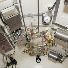
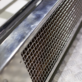
Chamber conditioning CCU-06
JFD's Divex chamber conditioning unit CCU-06 has been designed for use in hyperbaric environments, both air and heliox, for temperature and humidity control.
It is rated to depths of 500 MSW and form part of the extensive range of Divex hyperbaric environment conditioning equipment. The CCU-06 has been specifically designed for heating, cooling and dehumidification.
The unit may be mounted in any convenient space within the chamber where an even flow of circulating gas can be ensured, usually below chamber bunks. Flexible ducting may be added to the blower outlet to ensure adequate circulation, or to direct circulation into the required areas.
Interconnecting fluid supply pipework, shell stop valves, chamber temperature/humidity monitoring equipment and fluid temperature control systems, are not specified as these will tend to be unique for each application. The end-user should ensure these items are provided and installed to acceptable standards.
| CCU-06 | CCU-06 | CCU-06 | CCU-06 in HLB | CCU-06 in HLB |
|
|
|
|
|
|
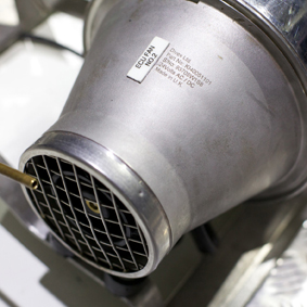
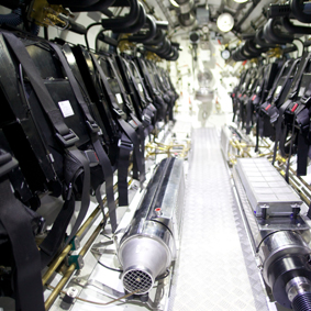
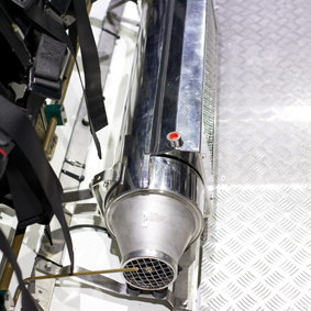
Components contained in the chamber conditioning units include:
- Coil assembly: heating and cooling coils fitted to common end plates forming a single coil assembly, mounted inside the heat exchanger box. Chamber atmosphere first passes through the cooling coil and then through the heating coil.
- Heat exchanger box: encloses heat exchanger assembly and includes hot and cold water connection ports and condensation drain ports for the CCU-06. Mounted onto plenum or duct assembly.
- Plenum or air duct assembly: positioned between the heat exchanger assembly and the blower assembly and includes mounting brackets.
- Blower assembly: produces the flow of breathing gas and includes electric motor.
*These are calculated values that need to be verified by testing in hyperbaric environments.
|
|
|
|
Electrical requirements |
24 VDC, ± 2A |
|
Air volume moved |
Up to 2m3/min |
|
Chilling/heating capacity* |
500 W @ 0 msw 4000 W @ 100 msw 8000 W @ 300 msw Heliox |
|
Condensation removal rate* |
0.2 ltrs/min |
|
Cooling/heating liquid |
25 ltrs/min |
|
Requirements |
Cold @ 2ºC, Hot @ 60ºC |
|
Coil construction |
Copper fins, stainless steel tubes and end plates |
|
Housing and blower assembly |
Gr. 316 stainless steel |
|
Heating/chilling fluid ports |
1/2" NPT (F) |
| Condensate drain ports | 1/2" NPT (F) x 4 off |
|
Coil external pressure test |
65 bar (hydro) |
|
Assembly leak test |
50 bar (helium) |
|
Mounting orientation |
Radiator fin plates in vertical plane for condensate drainage |
| Item | Order Code |
|
Chamber conditioning unit CCU-06, standard |
KI40053 |
|
Chamber conditioning unit CCU-06, Lloyds approved |
KI40053LYD |
|
Chamber conditioning unit CCU-06, DNV approved |
KI40053DNV |
|
Chamber conditioning unit CCU-06, ABS approved |
KI40053ABS |
| Document | Document type | Download |
|
Kinergetics chamber conditioning unit CCU-06 |
Datasheet | |
|
Chamber Conditioning Unit, CCU‐06, Part number: KI40053 |
Operation & Maintenance Manual | |
|
Kinergetics chamber conditioning unit CCU-06, axial blower 45 bar |
Drawing | KI40053S1 R1 |
| CCU-06 | CCU-06 | CCU-06 | CCU-06 in HLB | CCU-06 in HLB |
|
|
|
|
|
|
Components contained in the chamber conditioning units include:
- Coil assembly: heating and cooling coils fitted to common end plates forming a single coil assembly, mounted inside the heat exchanger box. Chamber atmosphere first passes through the cooling coil and then through the heating coil.
- Heat exchanger box: encloses heat exchanger assembly and includes hot and cold water connection ports and condensation drain ports for the CCU-06. Mounted onto plenum or duct assembly.
- Plenum or air duct assembly: positioned between the heat exchanger assembly and the blower assembly and includes mounting brackets.
- Blower assembly: produces the flow of breathing gas and includes electric motor.
*These are calculated values that need to be verified by testing in hyperbaric environments.
|
|
|
|
Electrical requirements |
24 VDC, ± 2A |
|
Air volume moved |
Up to 2m3/min |
|
Chilling/heating capacity* |
500 W @ 0 msw 4000 W @ 100 msw 8000 W @ 300 msw Heliox |
|
Condensation removal rate* |
0.2 ltrs/min |
|
Cooling/heating liquid |
25 ltrs/min |
|
Requirements |
Cold @ 2ºC, Hot @ 60ºC |
|
Coil construction |
Copper fins, stainless steel tubes and end plates |
|
Housing and blower assembly |
Gr. 316 stainless steel |
|
Heating/chilling fluid ports |
1/2" NPT (F) |
| Condensate drain ports | 1/2" NPT (F) x 4 off |
|
Coil external pressure test |
65 bar (hydro) |
|
Assembly leak test |
50 bar (helium) |
|
Mounting orientation |
Radiator fin plates in vertical plane for condensate drainage |
| Item | Order Code |
|
Chamber conditioning unit CCU-06, standard |
KI40053 |
|
Chamber conditioning unit CCU-06, Lloyds approved |
KI40053LYD |
|
Chamber conditioning unit CCU-06, DNV approved |
KI40053DNV |
|
Chamber conditioning unit CCU-06, ABS approved |
KI40053ABS |
| Document | Document type | Download |
|
Kinergetics chamber conditioning unit CCU-06 |
Datasheet | |
|
Chamber Conditioning Unit, CCU‐06, Part number: KI40053 |
Operation & Maintenance Manual | |
|
Kinergetics chamber conditioning unit CCU-06, axial blower 45 bar |
Drawing | KI40053S1 R1 |


